Selection of BBS rim parts
Selection of tire and width of the rim
In general the total width of the rim has to be selected corresponding to the tire width. The manufacturer of the tire specifies possible rim width for the selected tire. In case the rim width is not declared, the nominal rim width can be calculated as follows: nominal width of the tire contact surface divided by 25.4 results in the width of the rim in inch. For example: nominal width of the tire contact surface 175 mm divided by 25.4 mm results in app. 7” rim width.
Especially for racing tires the following has to be respected: In case a tire is applied to a rim that is too narrow, the tire wall can move on the rim and the tire heats up excessively. In case a tire is applied to a rim that is too wide the tire flank becomes stiff and the tire cannot reach the optimum temperature and grip.
It makes little sense to mount the same tire to a wider rim on the rear axle than on the front axle, because the effective width (contact surface) of the tire will not change. Only the flanks of the tire are positioned in the rim under different angle. In case of different rim width on front and rear axle, the use of different tires is possible. For example 7” front rim with 175 mm tire and 8” rear rim with 195 mm tire.
It has to be considered that a 7” wheel that is positioned more to the outside results in an effectively wider track width than an 8” wheel. This means that with an existing mudguard extension an 8” wheel can only be positioned more to the middle of the car and result in a smaller track width. The handling of the car at cornering in general will be improved by a wider track width.
Because of also the rolling friction and the air resistance of a wide tire increases, it makes little sense to select the tire width bigger than needed.
Selection of the rim halves
The width of a rim half is measured from the middle of the seal ring to the contact surface of the tire to the rim edge. This dimension measured in millimeter divided by 25.4 mm results in the width of the rim half in inch.
Based on the rim centre a three piece rim can be designed in consideration of rim width and rim offset.
The maximum width of the rim to the outboard side has to be selected under respect of the width and the design of the mudguard or existing mudguard extension. For the selection of the rim parts also the form of the tire wall of the mounted tire has to be considered, because the tire wall will get into contact to the mudguard first, in case of wheel movement at steering condition and spring compression.
In case the mudguards are still in original condition and the mudguard extensions have to be build it is recommended first to lower the car by the assembly of the final suspension. Also the selected wheels have to be tentatively assembled to the car during the enlarging process of the body.
During the enlargement process the wheel movement has to be checked. This means full compression to the mechanical end stop of the body arms and full steering condition. The simulation of the full spring compression can be realized as follows: the right front wheel and the left rear wheel of the car have to be put to 15 cm bases. The two other wheels must stay on the basement.
For the identification of the correct width of the rim halves also the width of the current assembled wheel can be helpful. For this the width and the rim offset of the wheel must be known.
As shown in the figure below the rim offset is defined as the distance between the middle of the rim and the flange of the rim centre. A positive rim offset of e.g. +25 mm (= +1”) means, that the middle of the rim is positioned 25 mm more to the middle of the car than the rim center flange. A negative rim offset means, that the middle of the rim relative to the rim center flange is positioned to the car outboard side.
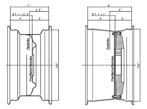
Figure: Rim offset on a steel rim and on the BBS three piece rim (examples).
The BBS rim centers and the rim centers Sälzer type S have no offset, what means, that the flange for the rim halves on the backside of the rim centre and the flange of the rim centre to the wheel hub are in one line. The shoulder on the backside of the rim centre equalizes the thickness of the outer rim half and the seal ring that are assembled to the backside of the rim centre.
For the design of a three piece rim similar to the current assembled rim the rim parts have to be selected as follows:
Outer BBS rim half:
Rim width of the current assembled rim divided by two minus rim offset.
Inner BBS rim half:
Rim width of the current assembled rim divided by two plus rim offset.
In case the calculation result can’t be split by half-inch, the next smaller rim halve has to be selected.
By the use of the Spiess rim centre, that due to its design results in one inch track enlargement, the outer rim halves have to be selected 1” smaller and the inner rim halves have to be selected 1” wider than with a flat rim centre.
Example:
The rim width of the currently assembled rim is 6” (6 multiplied with 25,4 mm result in 152 mm rim width). The rim offset of the current rim is 25 mm.
Selection of the outer BBS rim half: 152 mm divided by two minus 25 mm (offset) result in 51 mm. 51 mm divided by 25,4 mm = 2” width of the outer BBS rim half.
Selection of the inner BBS rim half: 152 mm divided by two plus 25 mm (offset) result in 101 mm. 101 mm divided by 25,4 mm = 4” width of the inner BBS rim half.
Check:
Total width of the BBS rim: 2” plus 4” = 6” as before.
Rim offset (middle of the BBS rim relative to the rim centre flange) 25 mm as before.
Note:
Please respect that our technical information are protected by copyright and are notarized. Any publication or use in total length, partial or redraft without our explicit consent we regrettably have to forbid.
|